SVIs and "Routed" Ports
So you have a this nice multiplayer switch, and want to take advantages of all of the features it has to offer. Well there are two different types interface ports on these type of switches. SVIs (Switched Virtual Interface) and "routed" ports, fundamentally they are same and clients/users wouldn't be able to tell if you were using/going through an SVI or a "routed" port. However they are different and in this post we'll talk about these two and when and were it would be recommended to place an SVI or a routed port.
In order to pass traffic between networks we need a router. Switches work in layer two and routers work in layer three, this separation of duties between devices works well. Doing something like Configuring Router on Stick, is easier to troubleshoot and usually cheaper to implement. It only becomes a problem when we run out of resources like bandwidth.
Looking on the example below, we have three different networks all branching off of this router. The router has three networks configured on this interface the red network, teal network and the blue network. In order for PC1 to reach PC2 it has use the router even through they are plugged on the same switch, they are on different VLANs, different networks. If PC1 was transferring a lot of data between PC2 it could easily tap out that router's interface. Other devices on those networks like PC3 would become bandwidth starved and struggle to get a good connection for inter-vlan connectivity. 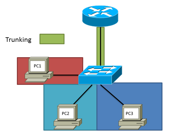
However a multilayered switch which has usually plenty of bandwidth on its back plane and would be able to handle this easily and in this example this would be great use case to create and SVI interface for each network. To create an SVI:
We have to have a VLAN created first, in this example lets use 105.
1switch(config)# vlan 105
2switch(config-vlan)# name RED-NETWORK
3switch(config-vlan)# exit switch(config)#
We then create an interface VLAN, referencing the VLAN we created in step one and apply an IP address and subnet mask on VLAN interface.
1switch(config)# interface vlan 105
2switch(config-if)# ip address 192.168.150.1 255.255.255.0
3switch(config-if)# no shutdown
4switch(config-if)# exit
On the interfaces that belong to that VLAN in this example PC1 apply the VLAN and verify the interface is in switchport mode.
1switch(config)# interface ethernet 1/1
2switch(config-if)# switchport
3switch(config-if)# switchport mode access
4switch(config-if)# switchport access vlan 105
5switch(config-if)# no shutdown
6switch(config-if)# exit
Here is the configuration for the TEAL Network, if we wanted to configure the BLUE network just put it into a different VLAN and separate IP network.
 1switch(config)# vlan 110
 2switch(config-vlan)# name TEAL-NETWORK
 3switch(config-vlan)# exit
 4switch(config)# interface vlan 110
 5switch(config-if)# ip address 192.168.160.1 255.255.255.0
 6switch(config-if)# no shutdown
 7switch(config-if)# exit
 8switch(config)# interface ethernet 1/2
 9switch(config-if)# switchport
10switch(config-if)# switchport mode access
11switch(config-if)# switchport access vlan 110
12switch(config-if)# exit
We can then verify that the switch has a routing table by issuing show ip route and if we also run the command show ip interface brief and you can see the interface-vlans
 1switch# show ip route
 2IP Route Table for VRF "default"
 3'*' denotes best ucast next-hop
 4'**' denotes best mcast next-hop
 5'[x/y]' denotes [preference/metric]
 6'%' in via output denotes VRF
 7
 8192.168.150.0/24, ubest/mbest: 1/0, attached
 9*via 192.168.150.1, Vlan105, [0/0], 00:06:03, direct
10192.168.150.1/32, ubest/mbest: 1/0, attached
11*via 192.168.150.1, Vlan105, [0/0], 00:06:03, local
12192.168.160.0/24, ubest/mbest: 1/0, attached
13*via 192.168.160.1, Vlan110, [0/0], 00:01:59, direct
14192.168.160.1/32, ubest/mbest: 1/0, attached
15*via 192.168.160.1, Vlan110, [0/0], 00:01:59, local
16
17switch# show ip interface brief
18
19IP Interface Status for VRF "default"(1)
20Interface            IP Address      Interface Status
21Vlan105              192.168.150.1   protocol-up/link-up/admin-up
22Vlan110              192.168.160.1   protocol-up/link-up/admin-up
23switch#
We can also verify that PC1 and PC2 can ping each other. PC2 pinging PC1
1PC-2> ping 192.168.150.10
2192.168.150.10 icmp_seq=1 timeout
3192.168.150.10 icmp_seq=2 timeout
484 bytes from 192.168.150.10 icmp_seq=3 ttl=63 time=15.258 ms
584 bytes from 192.168.150.10 icmp_seq=4 ttl=63 time=19.669 ms
684 bytes from 192.168.150.10 icmp_seq=5 ttl=63 time=19.113 ms
PC1 pinging PC2
1PC-1> ping 192.168.160.10
284 bytes from 192.168.160.10 icmp_seq=1 ttl=63 time=17.825 ms
384 bytes from 192.168.160.10 icmp_seq=2 ttl=63 time=19.710 ms
484 bytes from 192.168.160.10 icmp_seq=3 ttl=63 time=18.503 ms
584 bytes from 192.168.160.10 icmp_seq=4 ttl=63 time=18.577 ms
684 bytes from 192.168.160.10 icmp_seq=5 ttl=63 time=9.817 ms
SVI's are great for inter-vlan connectivity and for devices that are "physically" close to each other. I would shy away using an SVI when we are connecting different buildings/sites, and if we a using a some type of transit network to get from point A to point B. Using a routed port is not only easier to configure its easier to troubleshoot, we don't have worry about the problems layer two brings us, like for example redundancy and spanning-tree we just focus on layer three and the redundancies that layer three can offer us. In this example this switch is connected to another switch with multiple links using routed ports. To create a routed port:
Go into the interface and turn off switchport and add an IP address
1switch(config)# interface ethernet 1/4
2switch(config-if)# no switchport
3switch(config-if)# ip address 192.168.253.1 255.255.255.252
4switch(config-if)# no shutdown
5switch(config-if)# exit
If you have multiple routed ports for redundancy, add another routed port with a different network.
1switch(config)# interface ethernet 1/5
2switch(config-if)# no switchport
3switch(config-if)# ip add 192.168.253.5 255.255.255.252
4switch(config-if)# no shutdown
5switch(config-if)# exit
We would do the same thing on the other side of the link and make sure our networks match so that each switch can reach other out of the two routed ports we created and in this example they can.
 1switch(config)# show ip interface brief
 2
 3IP Interface Status for VRF "default"(1)
 4Interface            IP Address      Interface Status
 5Eth1/4               192.168.253.2   protocol-up/link-up/admin-up
 6Eth1/5               192.168.253.6   protocol-up/link-up/admin-up
 7switch(config)#
 8switch(config)# ping 192.168.253.1
 9PING 192.168.253.1 (192.168.253.1): 56 data bytes
1064 bytes from 192.168.253.1: icmp_seq=0 ttl=254 time=1.368 ms
1164 bytes from 192.168.253.1: icmp_seq=1 ttl=254 time=1.205 ms
1264 bytes from 192.168.253.1: icmp_seq=2 ttl=254 time=2.099 ms
1364 bytes from 192.168.253.1: icmp_seq=3 ttl=254 time=1.166 ms
1464 bytes from 192.168.253.1: icmp_seq=4 ttl=254 time=1.353 ms
15
16--- 192.168.253.1 ping statistics ---
175 packets transmitted, 5 packets received, 0.00% packet loss
18round-trip min/avg/max = 1.166/1.438/2.099 ms
19switch(config)# ping 192.168.253.5
20PING 192.168.253.5 (192.168.253.5): 56 data bytes
2164 bytes from 192.168.253.5: icmp_seq=0 ttl=254 time=1.45 ms
2264 bytes from 192.168.253.5: icmp_seq=1 ttl=254 time=1.28 ms
2364 bytes from 192.168.253.5: icmp_seq=2 ttl=254 time=0.995 ms
2464 bytes from 192.168.253.5: icmp_seq=3 ttl=254 time=1.408 ms
2564 bytes from 192.168.253.5: icmp_seq=4 ttl=254 time=1.303 ms
26
27--- 192.168.253.5 ping statistics ---
285 packets transmitted, 5 packets received, 0.00% packet loss
29round-trip min/avg/max = 0.995/1.287/1.45 ms
30switch(config)#
Although you could have created an SVI for these point to point links, I don't think there's a reason. We can configure multiple static routes or using a routing protocol to handle the links if they go down and we only deal with layer three, which is keeping it simple. Like always I hope this information is helpful. -Ryan