Configure Router on a Stick
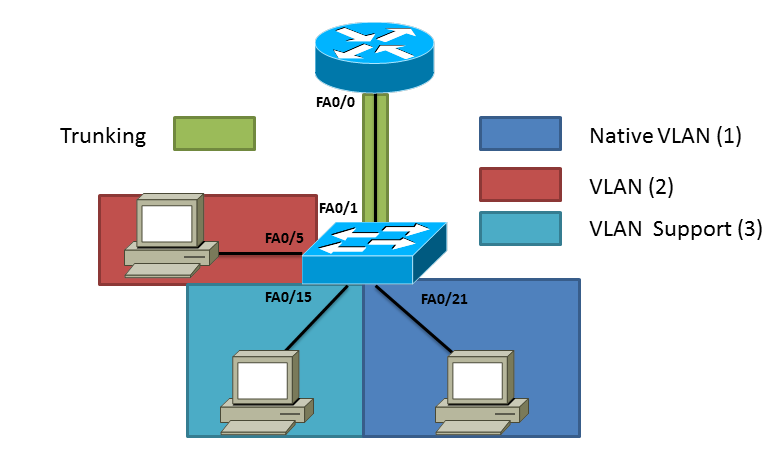
A while ago I talked about putting different VLANs on a switch, remember a VLAN is virtual network that although physically it may look like on the same network that does not always mean the case. By having VLANs you are segmenting the network and the only way to get to the other side is having a router. I have already configured the Cisco switch as posted in Creating VLANs but in summary I have three VLANs total VLAN 1 which is the native VLAN, VLAN 2 and VLAN 3 (which is called support. If you like to understand how create VLANs on a switch follow the post above. If you look at the network topology below you can see where Cisco came up with the name "Router on Stick" each PC is on its own network and needs the router in order for traffic to pass between the networks. Like before I have three VLANs total. VLAN 1 which is the native VLAN, VLAN 2 and VLAN 3 (which is called "Support").
You have to create sub-interfaces on the router to route between different VLANs these sub-interfaces do not correspond to the VLANs so you could put any number but for manageability usually people use the same sub-interface has the VLAN ID. To create a sub-interface start typing the interface that will be physically connected to the switch at the end add a period and number.
1Router#config t
2Enter configuration commands, one per line. End with CNTL/Z.
3Router(config)#interface fastEthernet 0/0.2
4Router(config-subif)#
You are now in the sub-interface configuration, we want to tell the router which VLAN this interface will be a part of. In this example I am typing "encapsulation dot1Q 2" dot1Q is an IEEE standard 802.1Q , the number "two" is the VLAN this interface will be a part of. Just like a real interface this interface must have an IP address for end devices to reach it. In this example we are using 192.168.2.1 with a Class C subnet mask. (i.e 255.255.255.0)
1Router(config-subif)#encapsulation dot1Q 2
2Router(config-subif)#ip address 192.168.2.1 255.255.255.0
3Router(config-subif)#no shut
We do the same for VLAN 3 (Support) in which we will create a new sub-interface in this example I am using sub-interface 3, and I'm going to be putting this sub-interface in VLAN 3 by using "encapsulation dot1Q 3". Remember the sub-interface number has no effect on which VLAN this interface is a part of. I'm also adding a IP address of 192.168.3.1 with a Class C subnet mask.
1Router#config t
2Enter configuration commands, one per line. End with CNTL/Z.
3Router(config)#interface fastEthernet 0/0.3
4Router(config-subif)#
5Router(config-subif)#encapsulation dot1Q 3
6Router(config-subif)#ip address 192.168.3.1 255.255.255.0
7Router(config-subif)#no shut
The last VLAN is the native VLAN and by default is VLAN 1, for this configuration go to the physical interface and add an IP address for this example we are using 192.168.1.1 with a Class C subnet mask.
1Router#config t
2Enter configuration commands, one per line. End with CNTL/Z.
3Router(config)#interface fastEthernet 0/0
4Router(config-if)#ip address 192.168.1.1 255.255.255.0
5Router(config-if)#no shut
The last thing we have to setup is on the Cisco Switch in which we have to specify which interface on the switch will pass all the VLANs, this is known as the trunking port. Go into configuration mode and for this example we selected FastEthernet0/1 apply the "switchport mode trunk" command and since we are using the default native VLAN which is not always recommended that's all the configuration needed. We now have three different networks separated by VLANs, if you issue a "show ip route" on the router we will see each sub-interface and route to each of them. All devices should be able to ping each other.
1Switch>en
2Switch#config t
3Enter configuration commands, one per line.  End with CNTL/Z.
4Switch(config)#interface fastEthernet 0/1
5Switch(config-if)#switchport mode trunk
 1Router#show ip route
 2Codes: C - connected, S - static, I - IGRP, R - RIP, M - mobile, B - BGP
 3       D - EIGRP, EX - EIGRP external, O - OSPF, IA - OSPF inter area
 4       N1 - OSPF NSSA external type 1, N2 - OSPF NSSA external type 2
 5       E1 - OSPF external type 1, E2 - OSPF external type 2, E - EGP
 6       i - IS-IS, L1 - IS-IS level-1, L2 - IS-IS level-2, ia - IS-IS inter area
 7       * - candidate default, U - per-user static route, o - ODR
 8       P - periodic downloaded static route
 9
10Gateway of last resort is not set
11
12C    192.168.1.0/24 is directly connected, FastEthernet0/0
13C    192.168.2.0/24 is directly connected, FastEthernet0/0.2
14C    192.168.3.0/24 is directly connected, FastEthernet0/0.3
I hope this information is helpful I have also attached a PDF of the running-config of both devices to give you an example of the configuration. (Router-On-Stick-Example-RunConfig) If you have any questions post them below. Like always if you an idea of the next topic let me hear it.
Related articles
- OSPF...What a Protocol! (lewiryan.github.io/ciscoskills)
- What is IPv6 ? An introduction to IPV6 (ipv6area.wordpress.com)
- Guest VLANS + Guest Wifi - Different IP Range, Out to Filtered Internet (edugeek.net)
- Journey to the CCIE LAB - Part 44 - BGP Link Bandwidth (mungauwamaseghe.wordpress.com)
Static Comments:
I saw your comment on not having to use the encap command when using the actual interface (fa0/0), but I was wondering, (since you typically see books and tutorials NOT using the actual interface, but instead, typically fa0/0.1), are there any other ramifications to using one as opposed to the other?? Fa0/0 as opposed to Fa0/0.1?? Thanks, Kevin
Besided the encapsulation command, are there any ramifications to using Fa0/0 for vlan 1 (instead of Fa0/0.1, as typically shown in ROAS configs)? Thanks, Kevin
Ryan -
Hey Kevin, The only reason this is set on the physical interface is because it is using un-tagged traffic also know as the native VLAN. You can't set the encapsulation dot1q on a physical interface only sub-interfaces. A better way to do this is use a sub-interface followed by: encapsulation dot1Q [VLAN-ID] native I don't see any problems with this method besides security and monitoring. For example If you wanted to see all traffic passing in and out of the physical interface using Netflow or SNMP you would not see that in this example, you would only see the native VLAN traffic. For security you should not use the native VLAN in production so this example it is not using best practices therefore I would not recommend it. This post goes along with another post I did about creating VLANs on a switch: http://lewiryan.github.io/ciscoskills/2011/04/01/creating-vlans/ Hope that Helps, Ryan
Part 1 – The Joys of Subnetting! | Cisco Skills -
[...] Configure Router on a Stick (lewiryan.github.io/ciscoskills) [...]
Part 2 – The Joys of Subnetttting – VLSM! | Cisco Skills -
[...] Configure Router on a Stick (lewiryan.github.io/ciscoskills) [...]
[...] Configure Router on a Stick [...]
Ryan -
If you are talking about the trunk link between the switch and the router it will pass up to the router and then be forwarded back down to the switch. So if you had a lot of traffic being forwarded between networks you could run into some bandwidth limits. To fix that you could configure a switch that does layer 3 routing and skip the router all together that way you would not be dependent on that one link to forward all of your traffic back and forth. The native VLAN by default is VLAN 1 and that can be changed. The only difference between a native VLAN and a regular VLAN is it passes un-tagged traffic. If you look at the router configuration I've setup, the physical interface (fa0/0) notice how I don't have to put the encapsulation, because this is traffic is not tagged with a VLAN. To answer you question you can put everything on a VLAN and forget about the default/native VLAN. A good practice to use is to change it to a non-default number something other than 1 and a VLAN that you are not using in your network. However make sure every switch has the correct native VLAN or you will get messages about native VLAN mismatched. Ryan
Philip -
Great article! Thanks for the info. I was talking to my friend about this last night and when I got into packet tracer I couldn't quite figure out how to assign multiple ip addresses to a single interface. I'm glad you took the time to write up this example.
Ryan -
Glad I could help. :) The configuration is pretty straight forward.
Thanks Ryan
Trunking Administrative Modes | Cisco Skills -
[...] Post navigation ← Previous [...]
EIGRP… The Basics | Cisco Skills -
[...] Configure Router on a Stick (lewiryan.github.io/ciscoskills) [...]
ITforMe -
Good post. Thanks for sharing. Can you confirm that with intervlan routing, that one would not run into the bandwidth limitations imposed by a traditional upstream router? (e.g. say, 50 ports feeding upstream to a physical router only to pipe back down into the switch). In other words, is a router on a stick configuration smart enough to know that if it needs to route across two VLANs that happen to live on the same port, that it isolates the flow of traffic to just that port? I'm also interested in what your thoughts are on the default VLAN 1. It seems that it is often more than just the factory VLAN, but that it may hold special characteristics and limitations (e.g. routing, etc.). If that is the case, would you suggest taking a new stack of switches, and making all of the untagged ports to the systems/workstations on something like VLAN101, with a PVID of 101, so as to prevent any traffic from going across the default VLAN?